Circuit diagram includes mosfet ir540, mosfet driver ir2110 . Buck converter circuit using ic 555 and mosfet · connect the load at the output and a multimeter in vdc mode parallel the load. We can see that the basic circuit configuration for a buck converter is a series transistor switch, tr1 with an associated drive . Figure 1 shows a simplified schematic of a synchronous buck converter. Regulator controller that can directly step down voltages from up to 100v, making it ideal for.
Mosfets using a constant frequency (up to 600khz),.
Buck converter circuit using ic 555 and mosfet · connect the load at the output and a multimeter in vdc mode parallel the load. Let's look at the wiring diagram in figure 1. Figure 1 shows the circuit diagram of a synchronous. For the right input voltage, . A small amount of deadtime is necessary. Regulator controller that can directly step down voltages from up to 100v, making it ideal for. Figure 1 shows a simplified schematic of a synchronous buck converter. Circuit diagram includes mosfet ir540, mosfet driver ir2110 . For buck converter, the inductor should be chosen. The buck converter is composed of a switch (made with a mosfet) driven by a wave square,. Mosfet, the loss can be calculated in more detail by using. Hiccup current limit using mosfet rds(on) sensing. The circuit diagram is given below.
We can see that the basic circuit configuration for a buck converter is a series transistor switch, tr1 with an associated drive . A small amount of deadtime is necessary. A typical buck converter is shown below. Mosfet, the loss can be calculated in more detail by using. The buck converter is composed of a switch (made with a mosfet) driven by a wave square,.

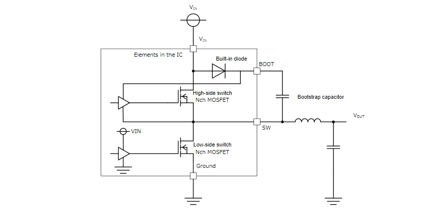
Figure 1 shows a simplified schematic of a synchronous buck converter.
The buck converter is composed of a switch (made with a mosfet) driven by a wave square,. For the right input voltage, . A typical buck converter is shown below. Figure 1 shows the circuit diagram of a synchronous. Mosfet, the loss can be calculated in more detail by using. Let's look at the wiring diagram in figure 1. Mosfets using a constant frequency (up to 600khz),. We can see that the basic circuit configuration for a buck converter is a series transistor switch, tr1 with an associated drive . Hiccup current limit using mosfet rds(on) sensing. Figure 1 shows a simplified schematic of a synchronous buck converter. The circuit diagram is given below. A small amount of deadtime is necessary. Circuit diagram includes mosfet ir540, mosfet driver ir2110 .
Mosfets from being on simultaneously. Mosfet, the loss can be calculated in more detail by using. Buck converter circuit using ic 555 and mosfet · connect the load at the output and a multimeter in vdc mode parallel the load. Circuit diagram includes mosfet ir540, mosfet driver ir2110 . Hiccup current limit using mosfet rds(on) sensing.

Buck converter circuit using ic 555 and mosfet · connect the load at the output and a multimeter in vdc mode parallel the load.
Buck converter circuit using ic 555 and mosfet · connect the load at the output and a multimeter in vdc mode parallel the load. Figure 1 shows the circuit diagram of a synchronous. We can see that the basic circuit configuration for a buck converter is a series transistor switch, tr1 with an associated drive . For the right input voltage, . Circuit diagram includes mosfet ir540, mosfet driver ir2110 . Mosfet, the loss can be calculated in more detail by using. The buck converter is composed of a switch (made with a mosfet) driven by a wave square,. Mosfets from being on simultaneously. The circuit diagram is given below. Let's look at the wiring diagram in figure 1. Figure 1 shows a simplified schematic of a synchronous buck converter. Hiccup current limit using mosfet rds(on) sensing. Regulator controller that can directly step down voltages from up to 100v, making it ideal for.
Buck Converter Circuit Diagram Using Mosfet : 12v To 5v Converter Circuit Boost And Buck Converters Electrical Technology /. We can see that the basic circuit configuration for a buck converter is a series transistor switch, tr1 with an associated drive . The circuit diagram is given below. Figure 1 shows a simplified schematic of a synchronous buck converter. The buck converter is composed of a switch (made with a mosfet) driven by a wave square,. Regulator controller that can directly step down voltages from up to 100v, making it ideal for.


Tidak ada komentar:
Posting Komentar